 +7 (495) 785-95-25
 +7 (495) 785-95-14
 sale@lcard.ru
 English version
Меню

+7 (495) 785-95-25
sale@lcard.ru
sale@lcard.ru
Стоимость по запросу
В наличии
Преимущества

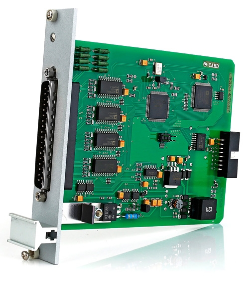
универсальный модуль с поддержкой большинства типов тензодатчиков и схем подключения под специфические требования
широкий выбор модификаций модулей семейства LTR212М для конкретных задач
программно-переключаемый источник опорного напряжения для питания тензодатчиков - с выходным напряжением +2,5 В или +5 В (постоянное или знакопеременное)
встроенный компенсационный ЦАП по каждому каналу АЦП для проведения компенсации начальной разбалансировки тензодатчиков без уменьшения динамического диапазона АЦП
входные аналоговые ФНЧ с дополнительной цифровой фильтрацией

| АЦП | |||||||||||||||||||||||||||||||||||||||||||||||||||||||||||||
| Количество каналов | 4/8 | ||||||||||||||||||||||||||||||||||||||||||||||||||||||||||||
| Разрядность АЦП | 24 бита, сигма-дельта АЦП | ||||||||||||||||||||||||||||||||||||||||||||||||||||||||||||
| Диапазон синфазных напряжений на измерительных входах (на”AIN+“и “AIN-“) относительно точки питания моста “-EXC” |
|
||||||||||||||||||||||||||||||||||||||||||||||||||||||||||||
| Коэффициент подавления входных синфазных помех при разбалансе сопротивлений внешних входных цепей, равном 1 кОм | Не менее 100 дБ | ||||||||||||||||||||||||||||||||||||||||||||||||||||||||||||
|
|||||||||||||||||||||||||||||||||||||||||||||||||||||||||||||
| Источник опорного напряжения (ИОН) | |||||||||||||||||||||||||||||||||||||||||||||||||||||||||||||
| Выходное напряжение ИОН (напряжение питания датчиков) | (2,5±0,1) В или (5±0,2) В, напряжение постоянного тока или знакопеременное (задается программно) | ||||||||||||||||||||||||||||||||||||||||||||||||||||||||||||
| Максимальный суммарный ток нагрузки | 400 мА | ||||||||||||||||||||||||||||||||||||||||||||||||||||||||||||
| Амплитудно-частотные характеристики и параметры встроенной цифровой фильтрации | |||||||||||||||||||||||||||||||||||||||||||||||||||||||||||||
| Максимальная частота дискретизации (для четырехканального режима) | 7600 Гц по каждому каналу | ||||||||||||||||||||||||||||||||||||||||||||||||||||||||||||
| Стабильность частоты преобразования одного модуля (в новых модификациях LTR212M частота преобразования АЦП синхронизирована с частотой опорного генератора крейта LTR) | ±50 ppm | ||||||||||||||||||||||||||||||||||||||||||||||||||||||||||||
| Полоса частот пропускания сигнала по уровню –3 дБ при отключенной цифровой фильтрации | 2000 Гц | ||||||||||||||||||||||||||||||||||||||||||||||||||||||||||||
| Цифровой перестраиваемый фильтр низкой частоты |
|
||||||||||||||||||||||||||||||||||||||||||||||||||||||||||||
| Гальваноизоляция модуля См. п.п. Характерные особенности модулей LTR |
|||||||||||||||||||||||||||||||||||||||||||||||||||||||||||||
| Различия модификаций | |||||||||||||||||||||||||||||||||||||||||||||||||||||||||||||
|
|||||||||||||||||||||||||||||||||||||||||||||||||||||||||||||
Примечание: "Л Кард" рекомендует пользователям в новых проектах переходить от LTR212 к LTR212M‑1, LTR212M‑2, LTR212M‑3
| Диапазон измерений напряжения постоянного тока положительной и отрицательной полярности или однополярный (поддиапазоны: ±80 мВ, 80 мВ, ±40 мВ, 40 мВ, ±20 мВ, 20 мВ, ±10 мВ, 10 мВ) | От 1 мкВ до 80 мВ |
|
Пределы допускаемой основной относительной погрешности измерений напряжения разбаланса моста
|
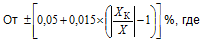 XК – конечное значение установленного поддиапазона измерений, мВ; X – показание LTR-212, мВ |
| Пределы допускаемой дополнительной относительной погрешности измерений напряжения разбаланса моста при изменении температуры окружающего воздуха на каждые 10 °С | Половина от пределов допускаемой основной относительной погрешности измерений |
| Входной ток смещения | Не более 50 нА |
| Входное сопротивление постоянному току | Не менее 10 МОм |
|
Нормальные условия применения |
|
| Температура окружающей среды | 20±5 °С |
| Относительная влажность | От 30 до 80 % |
| Атмосферное давление | От 84 до 106,7 кПа |
|
Рабочие условия применения |
|
| Температура окружающей среды | От +5 до +55 °С |
| Относительная влажность при температуре окружающей среды 25 °С | До 95 % |
| Атмосферное давление | От 70 до 106,7 кПа |
| LTR212M-1 | Цена по запросу |
| подключение до 4 четвертьмостов, 4 полумостов и 4/8 полных мостов, 0,5 Мбайт Flash-память, калибровка для ИОН 2,5 и 5В | |
| LTR212M-2 | Цена по запросу |
| подключение до 4 полумостов и 4/8 полных мостов, 0,5 Мбайт Flash-память, калибровка для ИОН 2,5 и 5В | |
| LTR212M-3 | Цена по запросу |
| подключение до 4 полумостов и 4/8 полных мостов, 256 байт EEPROM, калибровка для ИОН 5В | |
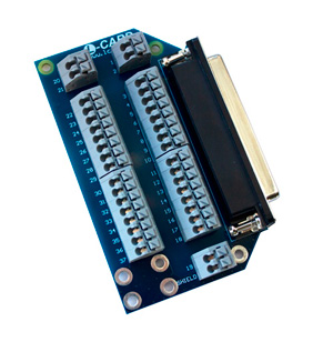
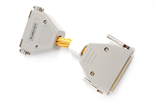
Коллекция мезонинов для установки на модуль LTR212M-1
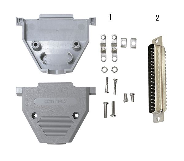
Плата клеммников на 37 контактнов
Синфазный помехоподавляющий фильтр
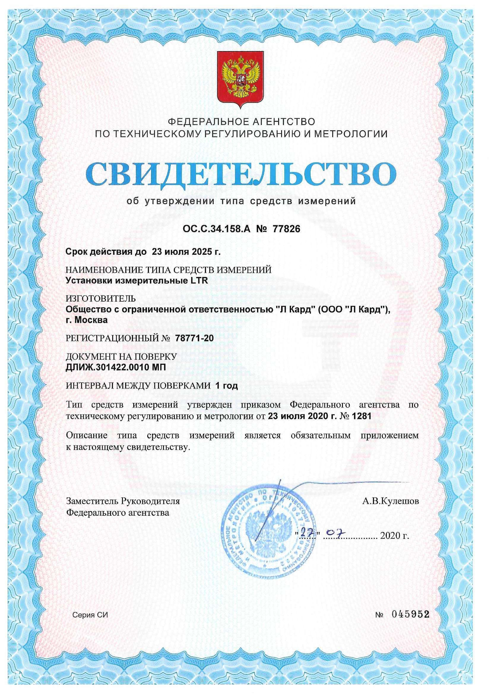
Описание типа: Установки измерительные LTR.
Свидетельство об утверждении типа средств измерений модульной системы LTR
Установки измерительные LTR. Методика поверки.
Общая 3D модель LTR модуля в формате PDF.
Для надлежащего отображение данного документа в используемой программе просмотра PDF файлов необходимо в её настройках включить поддержку 3D.
Например, для программы 'Adobe Acrobat Reader' это делается так.
Общая 3D модель LTR модуля в формате STP.
Начинаем работать с крейтовой системой LTR. Вопросы по
программному обеспечению.
Руководство для OPC-сервера "Л Кард"
Синфазный помехоподавляющий фильтр LTR-CMF. Руководство пользователя (ревизия 1.0.0).
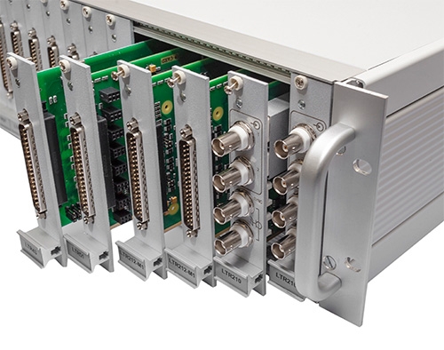
Крейтовая система LTR. Руководство пользователя (ревизия 4.0.0)
Модуль LTR-212. Библиотека Ltr212api. Руководство программиста.
Базовая библиотека Ltrapi. Руководство программиста.
Описание программного обеспечения под ОС Windows, Linux, FreeBSD и QNX
Таможенный союз. Декларация о соответствии.
А. В. Гарманов. Подключение измерительных приборов, решение вопросов электросовместимости и помехозащиты. L-Card, 2003.
Программный комплекс "L Card Measurement Studio" для проведения измерительных экспериментов с использованием оборудования "Л Кард". Версия 1.4.5.
Без приобретения ключа лицензии работает в демонстрационном режиме.
Описание программы.
Список изменений.
История изменений в версиях программного комплекса "L Card Measurement Studio".
Инструкция по установке программного комплекса "L Card Measurement Studio".
Инструкция по эксплуатации программного комплекса "L Card Measurement Studio".
Утилита для поверки модуля LTR212 под ОС Windows'XP/7/8.x/10/11.
Внимательно читаем Readme файл.
Использование открытых репозиториев исходных кодов
"Л Кард" на bitbucket.org
Использование внешних репозиториев "Л Кард" для
дистрибутивов Linux.
Проект "Л Кард" для распространения пакетов под различные дистрибутивы Linux с использованием Open Build Service.
Библиотека LCOMP под Windows'XP/Vista/7/8.x/10/11 (32-bit&64-bit) с драйверами для изделий от "Л Кард". Инсталлятор и драйвера имеют цифровую подпись. Библиотека построена на основе современных WDM-драйверов переписанных на WDF. Включает в себя собственно WDM-драйвера для оборудования "Л Кард", библиотеку DLL с исходными текстами, примеры программирования, электронное описание и т.д. Библиотека LCOMP обеспечивает поддержку почти всей гамме выпускаемых изделий: PCI платы, USB модули. Поддержка ISA плат прекращена.
Cоставной частью входит программа L-Graph I. В L-Graph I есть поддержка следующих устройств:
L-1450, L-761, L-780, L-783, L-791, E14-140, E-154 и E14-440. Файлы, записанные L-Graph I, могут быть также прочитаны и обработаны с помощью демо-версии программы PowerGraph v. 3.X
Служба ltrd. Версия 2.1.8.11.
Обеспечивает связь с крейтами LTR. Является заменой программы LTRserver с сохранением совместимости программного интерфейса. ltrd предназначен для той же цели, что и LTRserver, но представляет собой службу, запускающуюся вместе с запуском системы. При этом графический интерфейс к службе предоставляется отдельной программой LTR Manager.
Внимание!: Одновременно может работать только одна из программ ltrd или LTRserver.
Библиотеки для работы с крейтами и модулями LTR.
Версия 1.32.36
Программа LTR Manager. Версия 1.5.2.
Графический интерфейс к службе ltrd. Предоставляет интерфейс, схожий с интерфейсом программы LTRserver при работе через службу ltrd.
OPC-сервер для модулей сбора данных "Л Кард" и крейтовой системы LTR. Версия 1.1.4.
Руководство: http://www.lcard.ru/download/lcard-opc.pdf.
Без приобретения лицензии работает в демонстрационном режиме.
Исходные коды ltr_cross_sdk
Установщики ltrd, ltrmanager и ltrdll для ПК без поддержки SSE2 (Pentium III и ниже)
Тестовая программа ltrtest2 (требует наличия .NetFramework 2)
Примеры работы с OPC-сервером из LabView
Демонстрационная программа UTS для работы с крейтом LTR.
Версия 1.0.38.
LGraph2 - многофункциональная программа самописец-визуализатор под Windows'XP/7/8.x/10. Версия 2.36.2. Возможность одновременной визуализации и регистрации данных с АЦП L-502, L-780M, L-783, L-791, L-761, E-502, E14-140, E14-140M, E14-440, E-154, E20-10, LTR11, LTR114, LTR27, LTR212, LTR216, LTR22, LTR24, LTR25, LTR51, L-264, L-305, L-1250. Для работы программы требуется предварительно установить подписанные драйвера LComp и службу ltrd c графическим интерфейсом к ней LTR Manager.
История изменений и дополнений в версиях программы LGraph2.
Руководство пользователя программы LGraph2.
Руководство пользователя по разработке плагинов для программы LGraph2.
PowerGraph. Самописец-регистратор под Windows.
Разработка, поставка и техническая поддержка - ООО «ДИСофт». Подробнее см. www.powergraph.ru
Программа для настройки типа используемого интерфейса LTR крейта - USB или Ethernet. В случае использования LTR крейта по интерфейсу Ethernet, программа позволяет задать IP адрес устройства в сети, дежурный адрес шлюза, маску подсети.
Библиотеки для работы с крейтами и модулями LTR.
Версия 1.27.5
Библиотеки для работы с крейтами и модулями LTR. Версия 1.30.25
Инструкция и вспомогательные файлы для запуска ltrserver как службы Windows (с помощью программы nssm или srvany).
Программа LTRserver. Обеспечивает связь с крейтами LTR. Версия 1.5.5.2.
Добавлена поддержка LTR-CEU-1, LTR-CU-1
Исходные тексты ltrserver 1.5.5.2
Набор программ для поверки модулей LTR под ОС Windows'XP/7/8.x/10/11.
Исходные тексты программы ltrserver, старых версий библиотек и примеров. Исходные коды последних версий можно скачать со странички ltr_cross_sdk

Аппаратное описание, назначение и подключение сигналов приведены в Руководстве пользователя.
Адрес: 117105, Москва, Варшавское шоссе, д. 5, корп. 4, стр. 2
Многоканальный телефон:
+7 (495) 785-95-25
Факс: +7 (495) 785-95-14
Отдел продаж: sale@lcard.ru
Техническая поддержка: support@lcard.ru
Время работы: с 9-00 до 19-00 мск

 скачать презентацию
 скачать каталог продукции
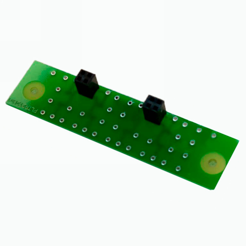