 +7 (495) 785-95-25
 +7 (495) 785-95-14
 sale@lcard.ru
 English version
Меню

+7 (495) 785-95-25
sale@lcard.ru
sale@lcard.ru
Стоимость по запросу
В наличии
Преимущества

фазочастотная характеристика близка к линейной, что минимизирует искажения фильтрации
антиалайзинговые фильтры для повышения качества оцифровки
режим резервированного подключения более одного LTR24 к одним и тем же источникам сигналов для систем повышенной надёжности
дискретизация до 117 кГц на канал позволяет решить широкий спектр задач вибродиагностики и акустики
4 входа для подключения ICP датчиков или тензорезисторов (для LTR24-2)
одновременно для четырёх каналов программно задаётся возможность измерения собственного нуля LTR24, что позволяет при необходимости скомпенсировать относительно большой температурный дрейф сигма-дельта АЦП

| Общие характеристики (LTR24-1, LTR24-2) | |||||||||||||||||||
| Количество каналов | 4 канала, каждый канал программно настраивается либо в режим дифференциального входа (входы X,Y), либо в режим подключения ICP датчиков (на разъеме модуля есть отдельные контакты для подключения ICP датчиков). Каждый канал имеет высококачественный дифференциальный высокоомный вход с высоким коэффициентом подавления синфазного сигнала. | ||||||||||||||||||
| Разрядность сигма-дельта АЦП | 20/24 бит в зависимости от настроек | ||||||||||||||||||
| Максимальная частота преобразования АЦП | 117 кГц | ||||||||||||||||||
| Минимальная частота преобразования АЦП | 610 Гц | ||||||||||||||||||
| Режим измерения собственного напряжения смещения нуля | Программируется одновременно для всех каналов | ||||||||||||||||||
| Режим AC «с компенсацией постоянной составляющей» или нормальный режим “DC+AC” | Программируется раздельно для каждого канала | ||||||||||||||||||
| Остаточное смещение нуля преобразователя в режиме “AC” | 5 мВ (на поддиапзоне ±10 В) 1 мВ (на поддиапзоне ±2 В) |
||||||||||||||||||
| Линейность фазочастотной характеристики (ФЧХ) | В режиме “AC+DC” ФЧХ линейная во всем частотном диапазоне. В режиме “AC” ФЧХ линейная, за исключением области низких частот (менее 5 Гц), где активное влияние на АЧХ оказывает механизм компенсации постоянной составляющей. | ||||||||||||||||||
| Синхронность каналов АЦП | Все 4 канала модуля LTR24 строго синхронны, относительный фазовый сдвиг – минимальный. | ||||||||||||||||||
| Фазовый сдвиг при многомодульном вводе | В пределах одного крейта LTR относительный фазовый сдвиг сбора данных между модулями LTR24 всегда останется постоянным во времени, | ||||||||||||||||||
| Возможные сочетания частоты преобразования АЦП, формата выходных данных АЦП и количества каналов |
Примечание: Ограничения для крейта LTR-U-1-4 см. в Руководстве пользователя |
||||||||||||||||||
| Потребляемая мощность (при ненагруженных выходах "+15V", "-15V") | 3,0 Вт (LTR24-1) 3,5 Вт (LTR24-2, ICP-входы не подключены) 3,5 Вт (LTR24-2, ICP-входы подключены, ток 3 мА) 4,6 Вт (LTR24-2, ICP-входы подключены, ток 10 мА) |
||||||||||||||||||
| Выходы питания внешних устройств ("+15V", "-15V") | |||||||||||||||||||
| Тип выхода питания | Двуполярный | ||||||||||||||||||
| Выходное напряжение | ±15 В | ||||||||||||||||||
| Номинальный выходной ток | 30 мА по каждому выходу относительно цепи AGND 10 мА (для LTR24-2 при задействованных ICP-входах) |
||||||||||||||||||
| Выходное сопротивление | 22 Ом по каждому выходу | ||||||||||||||||||
| Характеристики при работе с дифференциальными входами (LTR24-1, LTR24-2) | |||||||||||||||||||
| Поддиапазоны измерения входного сигнала | ±10 В, ± 2 В (пиковые значения) | ||||||||||||||||||
| Напряжение синфазного сигнала дифференциального входа | ±10 В (не зависит от поддиапазона) | ||||||||||||||||||
| Рабочий диапазон сигнала относительно AGND | ±12 В (на входах X, Y) | ||||||||||||||||||
| Рабочий диапазон компенсации постоянной составляющей сигнала в режиме AC | на поддиапазоне ±10 В:
на поддиапазоне ±2 В:
|
||||||||||||||||||
| Входной ток по линиям X1…X4, Y1…Y4 при напряжении ±10 В | ±0,2 нА (в нормальных условиях) ±3,0 нА (в рабочем диапазоне температур) |
||||||||||||||||||
| Предельно допустимое напряжение | ±20 В (на входах X1…X4, Y1…Y4) | ||||||||||||||||||
| Нижняя граница АЧХ | 0 Гц (в режиме DC+AC) 0,48 ±0,60 Гц, по уровню –3 дБ (в режиме AC) |
||||||||||||||||||
| Верхняя граница АЧХ | 0,49 от установленной частоты преобразования по уровню –3 дБ | ||||||||||||||||||
| Отношение сигнал/шум, типичное значение | 102 дБ | ||||||||||||||||||
| Отношение сигнал/(шум+гармоники) по синусоидальному сигналу (SINAD), типичное значение | 97 дБ | ||||||||||||||||||
| Коэфиициент нелинейных искаженией (THD), типичное значение | 100 дБ | ||||||||||||||||||
| Динамический диапазон, свободный от паразитных выбросов (SFDR), типичное значение | 101 дБ | ||||||||||||||||||
| Межканальное прохождение на частоте 5 кГц | Менее -90 дБ | ||||||||||||||||||
| Среднеквадратическое значение собственного шума, типичное значение, при закороченном входе |
|
||||||||||||||||||
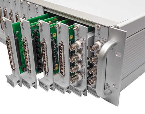
| Резервирование | Поддерживается возможность резервированного подключения (только по дифференциальному входу) более одного LTR24 к одним и тем же источникам сигналов. | ||||||||||||||||||
| Амплитудный спектр. Получен при подаче синусоидального сигнала 1,3 кГц на дифференциальные входы LTR24 для диапазона 2 В. Уровень “0 dB” на спектре соответствует максимальной амплитуде сигнала в установленном поддиапазоне. Используется БПФ на 20000 точек с окном Блэкмана-Харриса. |
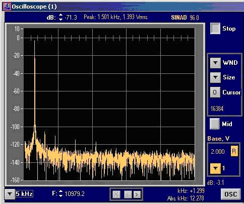 |
||||||||||||||||||
| Амплитудный спектр. Получен при подаче синусоидального сигнала 1,3 кГц на дифференциальные входы LTR24 для диапазона 10 В. Уровень “0 dB” на спектре соответствует максимальной амплитуде сигнала в установленном поддиапазоне. Используется БПФ на 20000 точек с окном Блэкмана-Харриса. |
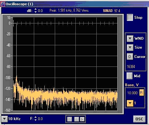 |
||||||||||||||||||
| Характеристики при работе с ICP-входами (LTR24-2) | |||||||||||||||||||
| Рабочий диапазон сигнала относительно AGND | От 0 до 22 В (на входах ICP) | ||||||||||||||||||
| Рабочий диапазон компенсации постоянной составляющей сигнала в режиме AC | От 0 до 22 В | ||||||||||||||||||
| Значение постоянного тока в цепи ICP-датчика при напряжении от 0 до 22 В | 10 мА ±2% (диапазон 10 мА) 2,86 мА ±2% (диапазон 2,86 мА) (20 мА или 5,72 мА – при параллельном включении пары входов ICP для одного датчика) |
||||||||||||||||||
| Нестабильность источника тока относительно калиброванного значения тока | ±0,05% от калиброванного значения (в нормальных условиях) ±0,15% от калиброванного значения (полном диапазоне температур) |
||||||||||||||||||
| Типичные значения входного сопротивление входа ICP |
25,7 кОм (на частоте сигнала 50 Гц) 25,5 кОм (на частоте сигнала 10 кГц) |
||||||||||||||||||
| Предельно допустимое напряжение | -1…+27 В при токе не более ±30 мА (на входах ICP1-ICP4) | ||||||||||||||||||
| Нижняя граница АЧХ | 1,3 Гц по уровню –3 дБ | ||||||||||||||||||
| Верхняя граница АЧХ | 0,49 от установленной частоты преобразования по уровню –3 дБ | ||||||||||||||||||
| Режим косвенных измерений сопротивления (LTR24-2) | |||||||||||||||||||
| Диапазоны измерений сопротивления в режиме “сопротивление DC+AC” | 0…1000 Ом (при токе 10 мА и диапазоне ±10 В) 0…3496 Ом (при токе 2,86 мА и диапазоне ±10 В) 0…200 Ом (при токе 10 мА и диапазоне ±2 В) 0…699 Ом (при токе 2,86 мА и диапазоне ±2 В) |
||||||||||||||||||
| Диапазоны измерений сопротивления в режиме измерения переменной составляющей сигнала “сопротивление AC” (в задачах виброметрии) | ±R/2 при сопротивлении датчика R=0…1000 Ом (при токе 10 мА и диапазоне ±10 В) ±R/2 при сопротивлении датчика R=0…3496 Ом (при токе 2,86 мА и диапазоне ±10 В) ±R/2 при сопротивлении датчика R=0…200 Ом (при токе 10 мА и диапазоне ±2 В) ±R/2 при сопротивлении датчика R=0…699 Ом (при токе 2,86 мА и диапазоне ±2 В) |
||||||||||||||||||
| Гальваноизоляция модуля См. п.п. Характерные особенности модулей LTR |
|||||||||||||||||||
| Диапазон измерений в режиме «Дифференциальный вход» (поддиапазоны: 10 и 2 В): - напряжения постоянного тока положительной и отрицательной полярности - напряжения переменного тока (амплитудное значение измеряемого напряжения не должно превышать конечного значения поддиапазона измерений) |
От 10 мкВ до 10 В От 10 мкВ до 10 В |
| Диапазон измерений в режиме «ICP-датчик» | От 1 мВ до 5 В |
| Пределы допускаемой основной относительной погрешности измерений напряжения постоянного тока положительной и отрицательной полярности в режиме «Дифференциальный вход» | 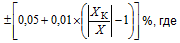 XК – конечное значение установленного поддиапазона измерений (XК = 10 В или 2 В); X – показание LTR24, В. |
| Пределы допускаемой основной относительной погрешности измерений среднеквадратического значения напряжения переменного тока в режиме «Дифференциальный вход» в диапазоне частот входного сигнала от 1 Гц до 50 кГц | 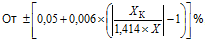 |
| Пределы допускаемой основной относительной погрешности измерений среднеквадратического значения напряжения переменного тока в режиме «ICP-датчик» в диапазоне частот входного сигнала от 0,1 до 50 кГц | 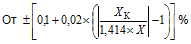 |
| Пределы допускаемой дополнительной относительной погрешности измерений напряжения постоянного и переменного тока при изменении температуры окружающего воздуха на каждые 10 °С | Половина от пределов допускаемой основной относительной погрешности измерений |
| Входное сопротивление постоянному току | Не менее 10 МОм |
| Межканальное прохождение входного напряжения постоянного и переменного тока частотой 5 кГц в режиме «Дифференциальный вход» | Не более минус 80 дБ |
| Коэффициент подавления синфазных помех для напряжения постоянного тока и переменного тока частотой 50 Гц в режиме «Дифференциальный вход» | Не менее 77 дБ |
| Коэффициент подавления помех общего вида для напряжения постоянного тока и переменного тока частотой 50 Гц в режиме «Дифференциальный вход» | Не менее 75 дБ |
|
Нормальные условия применения |
|
| Температура окружающей среды | 20±5 °С |
| Относительная влажность | От 30 до 80 % |
| Атмосферное давление | От 84 до 106,7 кПа |
|
Рабочие условия применения |
|
| Температура окружающей среды | От +5 до +55 °С |
| Относительная влажность при температуре окружающей среды 25 °С | До 95 % |
| Атмосферное давление | От 70 до 106,7 кПа |
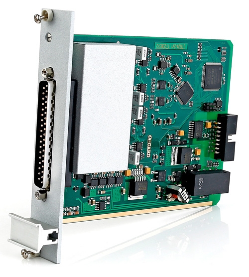
| LTR24-1 | Цена по запросу |
| 4 параллельных канала, 24 бит, до 117 кГц | |
| LTR24-2 | Цена по запросу |
| 4 параллельных канала, 24 бит, до 117 кГц, прямое подключение ICP датчиков | |
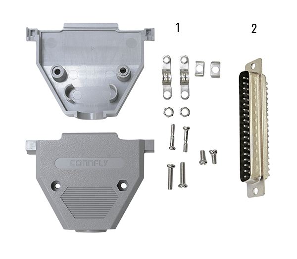
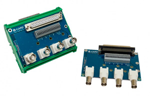
Плата клеммников на 37 контактнов
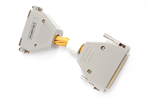
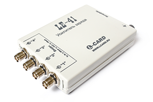
Синфазный помехоподавляющий фильтр
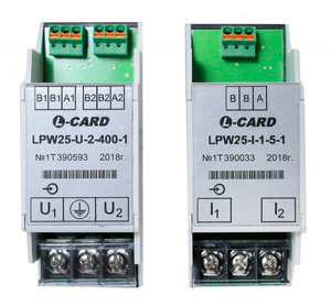
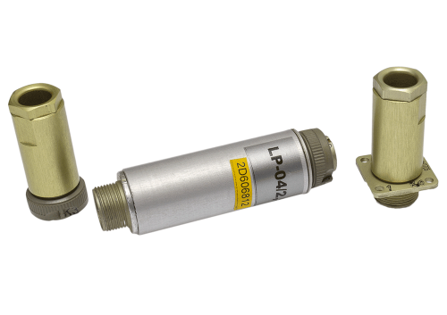
Универсальный предусилитель милливольтовых сигналов LP-04-M
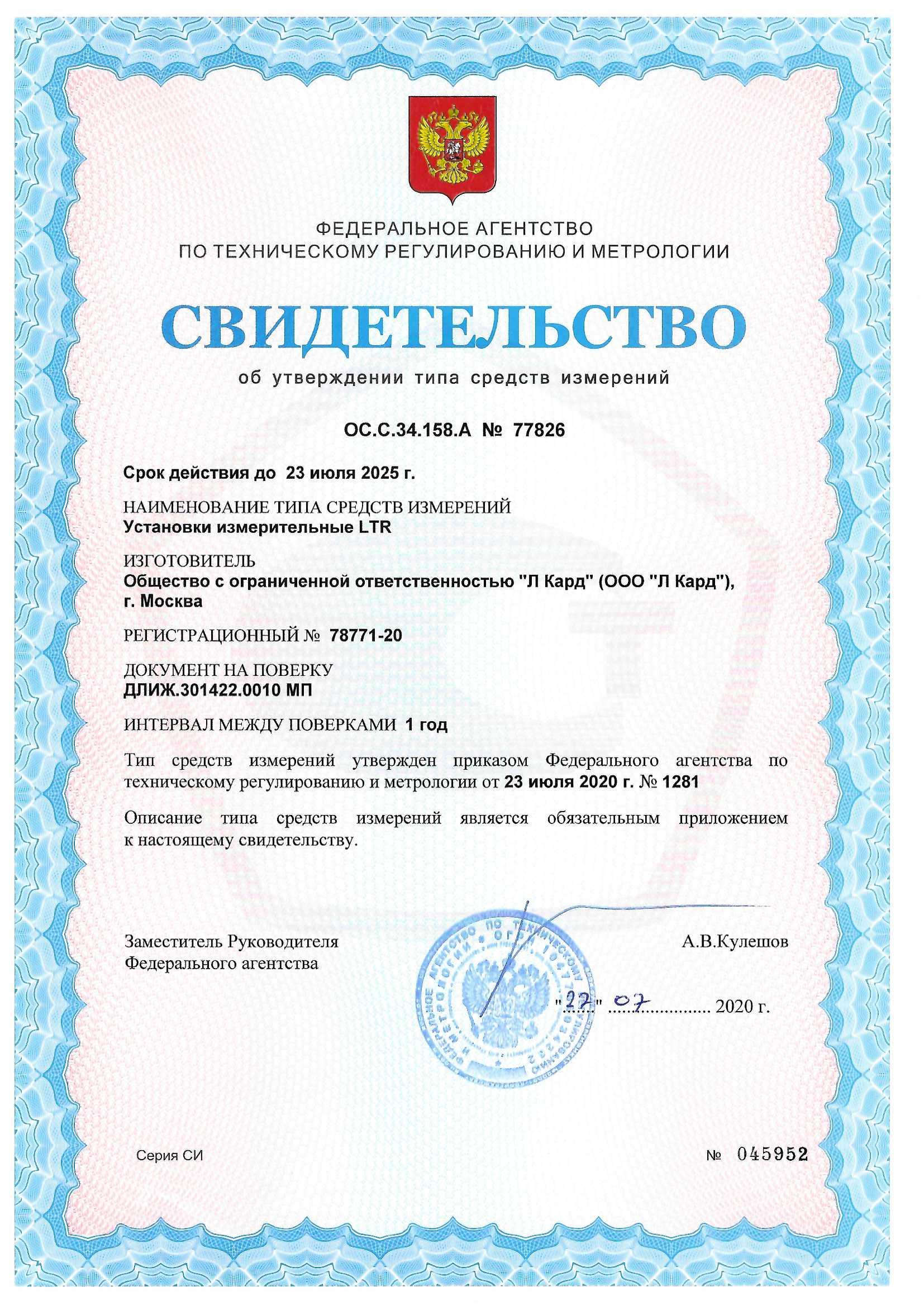
Описание типа: Установки измерительные LTR.
Свидетельство об утверждении типа средств измерений модульной системы LTR
Установки измерительные LTR. Методика поверки.
Общая 3D модель LTR модуля в формате PDF.
Для надлежащего отображение данного документа в используемой программе просмотра PDF файлов необходимо в её настройках включить поддержку 3D.
Например, для программы 'Adobe Acrobat Reader' это делается так.
Общая 3D модель LTR модуля в формате STP.
Начинаем работать с крейтовой системой LTR. Вопросы по
программному обеспечению.
Руководство для OPC-сервера "Л Кард"
Синфазный помехоподавляющий фильтр LTR-CMF. Руководство пользователя (ревизия 1.0.0).
Крейтовая система LTR. Руководство пользователя (ревизия 4.0.0)
Модуль LTR24. Руководство программиста.
Базовая библиотека Ltrapi. Руководство программиста.
Описание программного обеспечения под ОС Windows, Linux, FreeBSD и QNX
Таможенный союз. Декларация о соответствии.
А. В. Гарманов. Подключение измерительных приборов, решение вопросов электросовместимости и помехозащиты. L-Card, 2003.
А. В. Гарманов. Метод тонкой коррекции наклона АЧХ с помощью простого цифрового фильтра. L-Card, 2013
Программный комплекс "L Card Measurement Studio" для проведения измерительных экспериментов с использованием оборудования "Л Кард". Версия 1.4.5.
Без приобретения ключа лицензии работает в демонстрационном режиме.
Описание программы.
Список изменений.
История изменений в версиях программного комплекса "L Card Measurement Studio".
Инструкция по установке программного комплекса "L Card Measurement Studio".
Инструкция по эксплуатации программного комплекса "L Card Measurement Studio".
Утилита для поверки модуля LTR24 под ОС Windows'XP/7/8.x/10/11.
Внимательно читаем Readme файл.
Использование открытых репозиториев исходных кодов
"Л Кард" на bitbucket.org
Использование внешних репозиториев "Л Кард" для
дистрибутивов Linux.
Проект "Л Кард" для распространения пакетов под различные дистрибутивы Linux с использованием Open Build Service.
Библиотека LCOMP под Windows'XP/Vista/7/8.x/10/11 (32-bit&64-bit) с драйверами для изделий от "Л Кард". Инсталлятор и драйвера имеют цифровую подпись. Библиотека построена на основе современных WDM-драйверов переписанных на WDF. Включает в себя собственно WDM-драйвера для оборудования "Л Кард", библиотеку DLL с исходными текстами, примеры программирования, электронное описание и т.д. Библиотека LCOMP обеспечивает поддержку почти всей гамме выпускаемых изделий: PCI платы, USB модули. Поддержка ISA плат прекращена.
Cоставной частью входит программа L-Graph I. В L-Graph I есть поддержка следующих устройств:
L-1450, L-761, L-780, L-783, L-791, E14-140, E-154 и E14-440. Файлы, записанные L-Graph I, могут быть также прочитаны и обработаны с помощью демо-версии программы PowerGraph v. 3.X
Служба ltrd. Версия 2.1.8.11.
Обеспечивает связь с крейтами LTR. Является заменой программы LTRserver с сохранением совместимости программного интерфейса. ltrd предназначен для той же цели, что и LTRserver, но представляет собой службу, запускающуюся вместе с запуском системы. При этом графический интерфейс к службе предоставляется отдельной программой LTR Manager.
Внимание!: Одновременно может работать только одна из программ ltrd или LTRserver.
Библиотеки для работы с крейтами и модулями LTR.
Версия 1.32.36
Программа LTR Manager. Версия 1.5.2.
Графический интерфейс к службе ltrd. Предоставляет интерфейс, схожий с интерфейсом программы LTRserver при работе через службу ltrd.
OPC-сервер для модулей сбора данных "Л Кард" и крейтовой системы LTR. Версия 1.1.4.
Руководство: http://www.lcard.ru/download/lcard-opc.pdf.
Без приобретения лицензии работает в демонстрационном режиме.
Исходные коды ltr_cross_sdk
Установщики ltrd, ltrmanager и ltrdll для ПК без поддержки SSE2 (Pentium III и ниже)
Тестовая программа ltrtest2 (требует наличия .NetFramework 2)
Примеры работы с OPC-сервером из LabView
Демонстрационная программа UTS для работы с крейтом LTR.
Версия 1.0.38.
LGraph2 - многофункциональная программа самописец-визуализатор под Windows'XP/7/8.x/10. Версия 2.36.2. Возможность одновременной визуализации и регистрации данных с АЦП L-502, L-780M, L-783, L-791, L-761, E-502, E14-140, E14-140M, E14-440, E-154, E20-10, LTR11, LTR114, LTR27, LTR212, LTR216, LTR22, LTR24, LTR25, LTR51, L-264, L-305, L-1250. Для работы программы требуется предварительно установить подписанные драйвера LComp и службу ltrd c графическим интерфейсом к ней LTR Manager.
История изменений и дополнений в версиях программы LGraph2.
Руководство пользователя программы LGraph2.
Руководство пользователя по разработке плагинов для программы LGraph2.
Программа для настройки типа используемого интерфейса LTR крейта - USB или Ethernet. В случае использования LTR крейта по интерфейсу Ethernet, программа позволяет задать IP адрес устройства в сети, дежурный адрес шлюза, маску подсети.
Библиотеки для работы с крейтами и модулями LTR.
Версия 1.27.5
Библиотеки для работы с крейтами и модулями LTR. Версия 1.30.25
Инструкция и вспомогательные файлы для запуска ltrserver как службы Windows (с помощью программы nssm или srvany).
Программа LTRserver. Обеспечивает связь с крейтами LTR. Версия 1.5.5.2.
Добавлена поддержка LTR-CEU-1, LTR-CU-1
Исходные тексты ltrserver 1.5.5.2
Набор программ для поверки модулей LTR под ОС Windows'XP/7/8.x/10/11.
Исходные тексты программы ltrserver, старых версий библиотек и примеров. Исходные коды последних версий можно скачать со странички ltr_cross_sdk
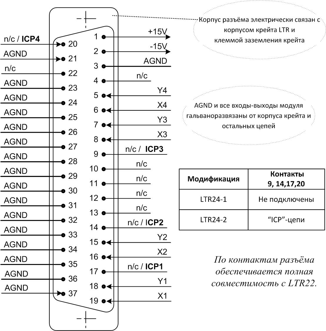
Аппаратное описание, назначение и подключение сигналов приведены в Руководстве пользователя.
Адрес: 117105, Москва, Варшавское шоссе, д. 5, корп. 4, стр. 2
Многоканальный телефон:
+7 (495) 785-95-25
Факс: +7 (495) 785-95-14
Отдел продаж: sale@lcard.ru
Техническая поддержка: support@lcard.ru
Время работы: с 9-00 до 19-00 мск

 скачать презентацию
 скачать каталог продукции
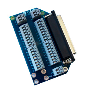