 +7 (495) 785-95-25
 +7 (495) 785-95-14
 sale@lcard.ru
 English version
Меню

+7 (495) 785-95-25
sale@lcard.ru
sale@lcard.ru
Стоимость от 122 218 руб.
В наличии
Преимущества

в комплект поставки входит все необходимое для работы с устройством
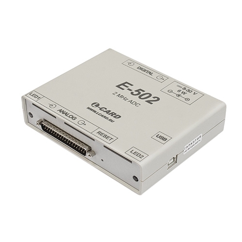
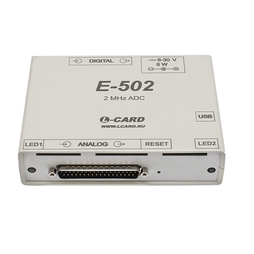
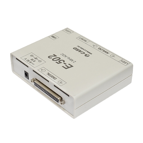
многофункциональный модуль АЦП/ЦАП с мощным сигнальным процессором и интерфейсами USB и Ethernet
16-разрядный АЦП обеспечивает высокую точность измерений
доступно индустриальное исполнение
разработан и серийно выпускается в России
гальваническая развязка, которая обеспечивает высокую помехоустойчивость
наличие подробного технического описания
наличие мощного сигнального процессора, который позволяет реализовывать алгоритмы обработки данных, не нагружая процессор ПК.

| АЦП | |||||||||||||||||||||||||||||||||||||||||||||||||||||
| Количество каналов | 16 дифференциальных или 32 с "общей землей" | ||||||||||||||||||||||||||||||||||||||||||||||||||||
| Разрядность АЦП | 16 бит | ||||||||||||||||||||||||||||||||||||||||||||||||||||
| Поддиапазоны измерения входного сигнала | ±10 В, ±5 В, ±2 В, ±1 В, ±0,5 В, ±0,2 В | ||||||||||||||||||||||||||||||||||||||||||||||||||||
| Максимальная частота преобразования АЦП | 2 МГц (1,5 МГц при синхронизации частоты преобразования от другого модуля E-502) |
||||||||||||||||||||||||||||||||||||||||||||||||||||
| Устойчивость к перегрузкам входным измерительным сигналом напряжения постоянного тока | ±15 В | ||||||||||||||||||||||||||||||||||||||||||||||||||||
| Синхронизация |
|
||||||||||||||||||||||||||||||||||||||||||||||||||||
| Защита входов | ±15 В | ||||||||||||||||||||||||||||||||||||||||||||||||||||
| Коэффициент подавления синфазного сигнала 50 Гц с амплитудой 1 В в дифференциальном режиме (на поддиапазонах) |
|
||||||||||||||||||||||||||||||||||||||||||||||||||||
| Собственный входной шум АЦП при закороченном входе в зависимости от поддиапазона АЦП и коэффициента усреднения отсчётов (Куср) по каждому каналу. |
|
||||||||||||||||||||||||||||||||||||||||||||||||||||
| Межканальное прохождение АЦП, дБ |
|
||||||||||||||||||||||||||||||||||||||||||||||||||||
| Цифровой сигнальный процессор (E-502-P-EU-D, E-502-P-EU-D-I) | |||||||||||||||||||||||||||||||||||||||||||||||||||||
| Тип |
ADSP-BF523 (E-502-P) GD32F450 (E-502-P1) |
||||||||||||||||||||||||||||||||||||||||||||||||||||
| ОЗУ | 32 Мбайт (SDRAM, 16 бит) | ||||||||||||||||||||||||||||||||||||||||||||||||||||
| Отладочные итерфейсы | JTAG, UART | ||||||||||||||||||||||||||||||||||||||||||||||||||||
| Энергонезависимакя память | |||||||||||||||||||||||||||||||||||||||||||||||||||||
| Flash-память |
2 МБ*) (E-502-P, E-502-X) 4 МБ*) (E-502-P1) *) Страница 1MБ доступна для хранения пользовательсой информации |
||||||||||||||||||||||||||||||||||||||||||||||||||||
| Гальваническая развязка | |||||||||||||||||||||||||||||||||||||||||||||||||||||
| Границы гальванических развязок | 1) Между всеми цепями, выходящими на контакты сигнальных разъёмов (Analog, Digital) и остальными цепями - низковольтная гальваническая изоляция (испытательное напряжение 400 В, 50 Гц в течение 1 мин). 2) В модификациях E-502-P-EU, E-502-P1-EU отдельную высоковольтную гальваническую изоляцию имеет Ethernet (испытательное напряжение 1500 В, 50 Гц в течение 1 мин). |
||||||||||||||||||||||||||||||||||||||||||||||||||||
| ЦАП (E-502-X-U-D, E-502-P-EU-D, E-502-P-EU-D-I) | |||||||||||||||||||||||||||||||||||||||||||||||||||||
| Количество выходов напряжения с общей землёй | 2 | ||||||||||||||||||||||||||||||||||||||||||||||||||||
| Тип ЦАП | Инструментальный | ||||||||||||||||||||||||||||||||||||||||||||||||||||
| Режимы вывода | Синхронный (потоковый), асинхронный, циклический автогенератор из внутреннего буфера E-502 (2 страницы по 1,5 Мотсч.) - воспроизведение напряжения постоянного и переменного тока | ||||||||||||||||||||||||||||||||||||||||||||||||||||
| Частота вывода в синхронном режиме | 1 МГц на каждый канал | ||||||||||||||||||||||||||||||||||||||||||||||||||||
| Выходной диапазон | ±5 В | ||||||||||||||||||||||||||||||||||||||||||||||||||||
| Рабочий выходной ток | Не более 10 мА | ||||||||||||||||||||||||||||||||||||||||||||||||||||
| Цифровые входы | |||||||||||||||||||||||||||||||||||||||||||||||||||||
| Общее количество цифровых TTL- совместимых входов общего назначения | 17 (четыре из них могут быть использованы для синхронизации) | ||||||||||||||||||||||||||||||||||||||||||||||||||||
| Режимы ввода данных | Синхронный, асинхронный | ||||||||||||||||||||||||||||||||||||||||||||||||||||
| Резисторные подтяжки к высокому логическому уровню | Отсутствуют (в отличие от L-502) | ||||||||||||||||||||||||||||||||||||||||||||||||||||
| Максимальная скорость в синхронном режиме | 2 МГц | ||||||||||||||||||||||||||||||||||||||||||||||||||||
| Рабочий диапазон напряжений |
-0,2...+0,6 В («логический ноль»), +2,4...+3,6 В («логическая единица» на входах DI14 / DI_SYN2, DI15 / СONV_IN, DI16 / START_IN), +2,4...+5,0 В («логическая единица» на остальных цифровых входах |
||||||||||||||||||||||||||||||||||||||||||||||||||||
| Высокоимпедансное состояние при выключенном питании | Присутствует | ||||||||||||||||||||||||||||||||||||||||||||||||||||
| Максимальный входной ток в при выключенном питании | 10 мкА | ||||||||||||||||||||||||||||||||||||||||||||||||||||
| Собственный входной ток в рабочем режиме при программно выключенных резисторных подтяжках | 10 мкА | ||||||||||||||||||||||||||||||||||||||||||||||||||||
| Цифровые выходы | |||||||||||||||||||||||||||||||||||||||||||||||||||||
| Общее количество TTL-совместимых цифровых выходов | 16 | ||||||||||||||||||||||||||||||||||||||||||||||||||||
| Управление третьим состоянием выходов | Присутствует | ||||||||||||||||||||||||||||||||||||||||||||||||||||
| Режимы вывода данных | Синхронный, асинхронный | ||||||||||||||||||||||||||||||||||||||||||||||||||||
| Максимальная скорость в синхронном режиме | 1 Мслов/c | ||||||||||||||||||||||||||||||||||||||||||||||||||||
| Предельно допустимый ток в цепи нагрузки | 20 мА | ||||||||||||||||||||||||||||||||||||||||||||||||||||
| Рекомендуемый ток в цепи нагрузки | Не более 8 мА | ||||||||||||||||||||||||||||||||||||||||||||||||||||
| Диапазон напряжений на цифровых выходах |
0...+0,4 В («логический ноль») Не менее 2,4 В («логическая единица»), выходные логические элементы с напряжением питания 3,3 В. |
||||||||||||||||||||||||||||||||||||||||||||||||||||
| Выходное сопротивление, типичное значение | 110 Ом | ||||||||||||||||||||||||||||||||||||||||||||||||||||
| Максимальный ток утечки в рабочем режиме в высокоимпедансном состоянии | ±1 мкА | ||||||||||||||||||||||||||||||||||||||||||||||||||||
| Высокоимпедансное состояние при выключенном питании | Отсутствует | ||||||||||||||||||||||||||||||||||||||||||||||||||||
| Многомодульная синхронизация | |||||||||||||||||||||||||||||||||||||||||||||||||||||
| Топология многомодульных соединений по линиям синхронизации | Короткие витые пары между цифровыми разъёмами «ведущего» и «ведомых» модулей. | ||||||||||||||||||||||||||||||||||||||||||||||||||||
| Частота межмодульной синхронизцации |
1,5 МГц (E-502-P, E-502-X) 1,5 МГц; 2,0 МГц (E-502-P1) |
||||||||||||||||||||||||||||||||||||||||||||||||||||
| Интерфейс с комьютером | |||||||||||||||||||||||||||||||||||||||||||||||||||||
| Формат слова данных | 32 бит (отчёт данных + индексная часть) | ||||||||||||||||||||||||||||||||||||||||||||||||||||
|
Скорость передачи данных по USB 2.0 (High Speed) |
5 Мотсч./c на ввод и вывод. |
||||||||||||||||||||||||||||||||||||||||||||||||||||
| Скорость передачи данных по Ethernet 100BASE-TX (E-502-P-EU) | До 2,5 Мотсч./c на ввод при физической скорости Ethernet 100 Mбит/с. Внимание! Режим 10 Mбит/с Ethernet не поддерживается. |
||||||||||||||||||||||||||||||||||||||||||||||||||||
| Интерфейсный микроконтроллер в E-502 |
LPC4333, LPC4337 или LPC4357 с отладочными интерфейсами UART и JTAG (E-502-P, E-502-X). CH32V307 с отладочными интерфейсами UART и JTAG (E-502-P1). |
||||||||||||||||||||||||||||||||||||||||||||||||||||
| Конструктивные характеристики | |||||||||||||||||||||||||||||||||||||||||||||||||||||
| Габариты | Не более 142 x 117 x 40 мм | ||||||||||||||||||||||||||||||||||||||||||||||||||||
| Масса | Не более 0,3 кг | ||||||||||||||||||||||||||||||||||||||||||||||||||||
| Питание E-502 | |||||||||||||||||||||||||||||||||||||||||||||||||||||
| Блок питания (сетевой адапер входит в комплект поставки) | ~220В/=12В, не менее 0.5A (данные о типе и температурном диапазоне сетевого адаптера - по запросу в отделе продаж) | ||||||||||||||||||||||||||||||||||||||||||||||||||||
| Диапазон напряжений входа низковольтного питания E-502 | +8...+30 В | ||||||||||||||||||||||||||||||||||||||||||||||||||||
| Максимальная мощность потребления от источника питания | 6 Вт | ||||||||||||||||||||||||||||||||||||||||||||||||||||
| Ток потребления по цепи питания интерфейса USB (в случае подключения USB) | Незначительный, менее 5 мА | ||||||||||||||||||||||||||||||||||||||||||||||||||||
| Питание внешних цепей | |||||||||||||||||||||||||||||||||||||||||||||||||||||
| Выходы питания внешних аналоговых и цифровых цепей |
+15 В, -15 В, +3,3 В (значения максимальных токов см. в Руководстве пользователя, п. 5.7) |
||||||||||||||||||||||||||||||||||||||||||||||||||||
|
АЦП |
|
| Диапазон измерений напряжения постоянного тока | От -10 до +10 В |
|
Пределы допускаемой приведенной (к верхнему значению предела
измерений) основной погрешности измерений напряжения постоянного
тока для пределов:
– 10; 5 и 2 В
– 1 В
– 0,5 В
– 0,2 В
|
±0,05 %
±0,07 %
±0,1 %
±0,2 %
|
| Диапазон измерений напряжения переменного тока в диапазоне частот от 0,01 до 999 кГц |
От 0,2 мВ до 7 В |
| Пределы допускаемой относительной основной погрешности измерений напряжения переменного тока 2) |
 XAC – предел измерений напряжения переменного тока; X – значение измеряемого напряжения переменного тока |
| Входное сопротивление постоянному току в одноканальном режиме работы |
Не менее 20 МОм |
| Коэффициент подавления синфазных помех | Не менее 70 дБ |
| Пределы допускаемой относительной основной погрешности частоты преобразований АЦП | ±0,005 % |
| ЦАП (E-502-X-U-D, E-502-P-EU-D, E-502-P-EU-D-I, E-502-P1-EU-D2-A1-I) | |
| Диапазон воспроизведений напряжения постоянного тока | От -5 до +5 В |
| Пределы допускаемой приведенной (к верхней границе диапазона воспроизведений) основной погрешности воспроизведений напряжения постоянного тока | ±0,1 % |
| Диапазон воспроизведений напряжения переменного тока синусоидальной формы в диапазоне частот от 0,01 до 100 кГц | От 1 мВ до 3,5 В |
| Пределы допускаемой относительной основной погрешности воспроизведений напряжения переменного тока 2) | XAC – конечное значение диапазона воспроизведений напряжения переменного тока, XAC = 3,5 В; X – значение воспроизводимого напряжения переменного тока |
| Пределы допускаемой относительной основной погрешности воспроизведений частоты переменного тока | ±0,005 % |
|
Условия эксплуатации |
|
|
Нормальные условия применения |
|
| Температура окружающей среды | 20±5 °С |
| Относительная влажность | От 30 до 80 % |
| Атмосферное давление | От 84 до 106 кПа |
|
Рабочие условия применения E-502-X-U-X, E-502-X-U-D, E-502-X-EU-X, E-502-P-EU-D |
|
| Температура окружающей среды | От +5 до +55 °С |
| Относительная влажность при температуре окружающей среды 25 °С | До 90 % |
| Атмосферное давление | От 70 до 106,7 кПа |
|
Рабочие условия применения E-502-P-EU-D-I, E-502-P1-EU-D2-A1-I |
|
| Температура окружающей среды | От -40 до +60 °С |
| Относительная влажность при температуре окружающей среды 30 °С | До 90 % |
| Атмосферное давление | От 70 до 106,7 кПа |
| Пределы допускаемых дополнительных погрешностей измерений напряжения постоянного и переменного тока, воспроизведений напряжения постоянного и переменного тока, частоты переменного тока, частоты преобразований АЦП от изменения температуры окружающей среды в диапазоне рабочих температур, на каждые 10 ºC, в долях от пределов допускаемой основной погрешности | 0,5 |

| E-502-X-U-X | Цена 122217.60 руб./шт. Минимальная партия для заказа 20 шт. |
| Модуль без процессора Blackfin, без ЦАП, без Ethernet | |
| E-502-X-EU-X | Цена 125020.45 руб./шт. Минимальная партия для заказа 20 шт. |
| Модуль без процессора Blackfin, без ЦАП | |
| E-502-X-U-D | Цена 127276.65 руб./шт. Минимальная партия для заказа 20 шт. |
| Модуль без процессора Blackfin, с ЦАП, без Ethernet | |
| E-502-P-EU-D | Цена 140080.00 руб. |
| Модуль с процессором Blackfin, с ЦАП, с интерфейсами USB 2.0 и Ethernet | |
| E-502-P-EU-D-I-m | Цена 146462.00 руб./шт. Минимальная партия для заказа 20 шт. |
| Модуль с процессором Blackfin, с ЦАП, с интерфейсами USB 2.0 и Ethernet, индустриальный, с поверкой | |
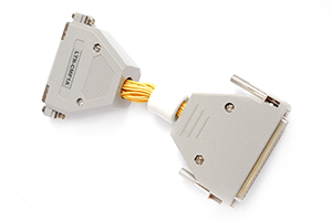
Плата клеммников на 37 контактнов
Синфазный помехоподавляющий фильтр
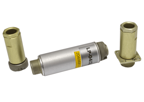
Универсальный предусилитель милливольтовых сигналов LP-04-M
* только для модификаций E-502-X-EU-X(-I), E-502-P-EU-D(-I)

Декларация о соответствии Техническим регламентам Таможенного Союза (ТР ТС)
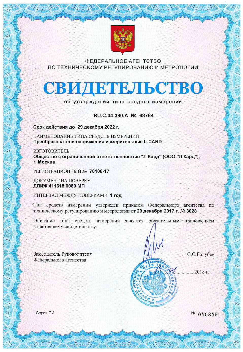
Свидетельство об утверждении типа средств измерений. Преобразователи напряжения измерительные L-CARD.
Модификации преобразователей:
Приказ о продлении действия 'Свидетельства об утверждении типа средств измерений' до 29.12.2027.
Преобразователи напряжения измерительные L-CARD: E14-140, E14-440, E20-10, E-502 и L-502.
Методика поверки.
3D модель модуля E-502 в формате PDF.
Для надлежащего отображение данного документа в используемой программе просмотра PDF файлов необходимо в её настройках включить поддержку 3D.
Например, для программы 'Adobe Acrobat Reader' это делается так.
3D модель модуля E-502 в формате STP.
E-502 Преобразователь напряжения измерительный.
Быстрый старт.
Руководство пользователя на модуль E-502.
Преобразователи напряжения измерительные L-CARD: E14-140, E14-440, E20-10, E-502 и L-502.
Руководство по эксплуатации.
Руководство программиста для модулей L502 и E502 в формате Adobe Acrobat.
Низкоуровневое руководство программиста для модулей L502 и E502.
Программный комплекс "L Card Measurement Studio" для проведения измерительных экспериментов с использованием оборудования "Л Кард". Версия 1.4.5.
Без приобретения ключа лицензии работает в демонстрационном режиме.
Описание программы.
Список изменений.
История изменений в версиях программного комплекса "L Card Measurement Studio".
Инструкция по установке программного комплекса "L Card Measurement Studio".
Инструкция по эксплуатации программного комплекса "L Card Measurement Studio".
Набор утилит для поверки изделий E-502 и L-502 под ОС Windows'XP/7/8.x/10/11.
Внимательно читаем Readme файл.
Использование открытых репозиториев исходных кодов
"Л Кард" на bitbucket.org
Использование внешних репозиториев "Л Кард" для
дистрибутивов Linux.
Проект "Л Кард" для распространения пакетов под различные дистрибутивы Linux с использованием Open Build Service.
OPC-сервер для модулей сбора данных "Л Кард" и крейтовой системы LTR. Версия 1.1.4.
Руководство: http://www.lcard.ru/download/lcard-opc.pdf.
Без приобретения лицензии работает в демонстрационном режиме.
L-Card L502/E502 SDK. Версия 1.1.24. Включает в себя драйвер, библиотеки, файлы для разработки программ и примеры программирования для модулей L502 и E502 фирмы ООО "Л Кард" под ОС Windows (поддерживаются версии Windows, начиная с Windows XP SP3 и выше, включая 64-битные версии).
Демонстрационная программа для модулей E-502 и L-502
LGraph2 - многофункциональная программа самописец-визуализатор под Windows'XP/7/8.x/10. Версия 2.36.2. Возможность одновременной визуализации и регистрации данных с АЦП L-502, L-780M, L-783, L-791, L-761, E-502, E14-140, E14-140M, E14-440, E-154, E20-10, LTR11, LTR114, LTR27, LTR212, LTR216, LTR22, LTR24, LTR25, LTR51, L-264, L-305, L-1250. Для работы программы требуется предварительно установить подписанные драйвера LComp и службу ltrd c графическим интерфейсом к ней LTR Manager.
История изменений и дополнений в версиях программы LGraph2.
Руководство пользователя программы LGraph2.
Руководство пользователя по разработке плагинов для программы LGraph2.
Исходные коды прошивки контроллера ARM Cortex-M4 для модификации E-502-P.
Для модификации E-502-P1 исходные коды прошивки сигнального процессора GD Cortex-M4 и интерфейсного микроконтроллера WCH RISC-V предоставляются по запросу в тех.поддержку.
Прошивка контроллера ARM Cortex-M4 для модификации E-502-P. Версия 1.0.23. Для обновления можно использовать программу X502Studio.

Аппаратное описание, назначение и подключение сигналов приведены в Руководстве пользователя.
Адрес: 117105, Москва, Варшавское шоссе, д. 5, корп. 4, стр. 2
Многоканальный телефон:
+7 (495) 785-95-25
Факс: +7 (495) 785-95-14
Отдел продаж: sale@lcard.ru
Техническая поддержка: support@lcard.ru
Время работы: с 9-00 до 19-00 мск

 скачать презентацию
 скачать каталог продукции
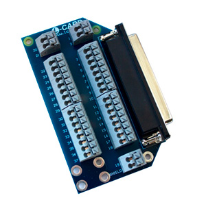
